Gene Editing and Facility Retrofits for CRISPR and Beyond

With the approval of the first gene edited therapeutic in 2023, production of gene edited therapies is accelerating, introducing tough decisions for manufacturing development. Gene editing therapy production is complex, often involving multi-modality manufacturing operations in one facility to produce a single therapeutic. This article considers whether retrofitting an aging monoclonal antibody (mAb) facility for the manufacture of a gene editing therapy could be a solution.
BACKGROUND
Since the discovery of the CRISPR-Cas system’s ability to edit genes in 2012, interest in gene editing as a therapeutic has accelerated. This is due to its potential to provide curative therapies for some of the most severe and often fatal genetic diseases. Gene editing is the process of adding, deleting, altering, or replacing DNA sequences at specific locations. In 2023, Vertex Pharmaceuticals and CRISPR Therapeutics obtained UK approval of the first gene edited product, an ex vivo gene edited stem cell therapy product for the treatment of sickle cell disease and transfusion-dependent beta thalassemia.
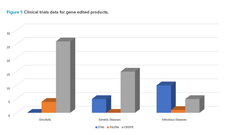
Figure 1 provides some data on the range of gene edited products in various phases of research and clinical trials as well as intended applications for prospective therapeutics.
| Gene Editing Technology | Zinc Finger Nucleases (ZFNs) | Transcription-Like Effector Nucleases (TALENs) | Clustered Regularly Interspaced Short Palindromic Repeats (CRISPR-Cas) | Base Editing |
|---|---|---|---|---|
| Discovery | 1985 | 2011 | 2012 | 2016 |
| Binding Technology | Protein-DNA | Protein-DNA | RNA-DNA | RNA-DNA |
| Endonuclease Technology | FokI Nuclease | FokI Nuclease | Cas9 Nuclease | Cas9 Nickase |
| Double Stranded Break Induced | Yes | Yes | Yes | No |
| Editing Capabilities | Knockin Knockout | Knockin Knockout | Knockin Knockout | Base Swapping |
| Companies Utilizing Technology | Sangamo | Cellectis | Caribou | Beam Therapeutics Verve Therapeutics |
Gene Editing Therapy Manufacturing
Due to a complex manufacturing process, gene editing therapy often involves multi-modality manufacturing operations in one facility. With development of any new therapeutic, there is also uncertainty as to whether a therapy will make it through clinical trials to a commercialized product. Modern trends also focus on the most sustainable approaches to implementing new manufacturing capacity. Considering these factors, retrofitting old assets may be a better solution than building new facilities to develop the required manufacturing capacity for a new gene editing therapy.
Gene Editing Primer
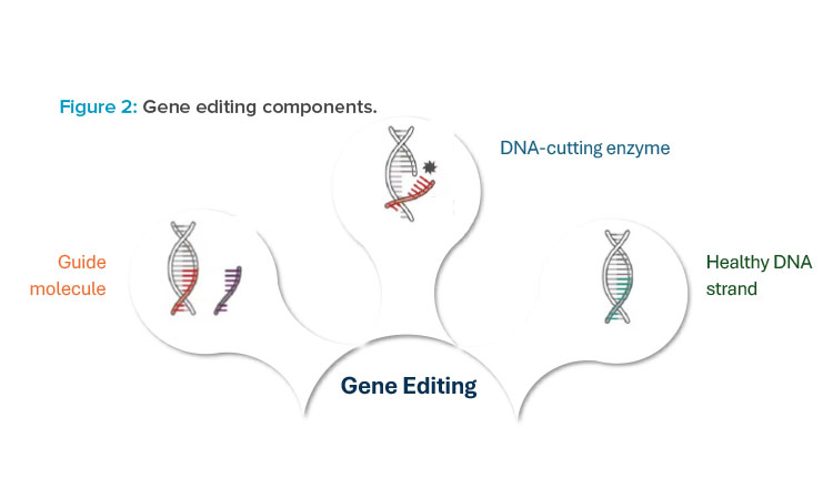
At its core, gene editing technology is composed of two to three different components, each of which is functionally crucial to deliver a gene editing therapy to patients. The first component is the guide molecule, which is used to target a precise location within the patient’s DNA where edits need to occur. The guide molecule can be either a protein or ribonucleic acid (RNA) sequence that is complementary to the corresponding DNA sequence of the patient. Figure 2 illustrates three different components that are used with gene editing technologies.
The second component is the DNA-cutting enzyme, or endonuclease. This molecule acts as the “molecular scissors” to cut the DNA at a precise location, allowing for edits to occur 1. Once the DNA is cut, there are two predominant mechanisms for repair of the double-strand break: non-homologous end joining (NHEJ) and homology directed repair (HDR). NHEJ is used to make genes nonfunctional, also referred to as a gene knockout. HDR provides new genetic material to correct a defective gene sequence and is referred to as a gene knocking. This mechanism requires a third component to be provided to the patient, a donor DNA template, for effective gene editing.
For each of these three components, there are several formats that can be used for manufacturing production and, in turn, delivery to patients. These include ribonucleoprotein (RNP) complex; viral delivery, commonly through use of a viral vector such as adeno-associated virus (AAV); and non-viral delivery, commonly through lipid nanoparticle (LNP) mediated delivery of guide RNA (gRNA) and messenger RNA (mRNA). These modality options will be discussed further in the upcoming sections.
GENE EDITING TECHNOLOGY
Although CRISPR is the most referenced gene editing technology, it is not the only option used in pre-clinical or clinical studies. Several different technologies are available for gene editing, each with its own bespoke design of the guide molecule and nuclease. Table 1 summarizes some of the more pertinent details of each type of technology.
Zinc Finger Nucleases (ZFNs)
ZFNs were the earliest gene editing technology with applications for human genome editing. With ZFNs, the guide molecule is composed of zinc finger proteins. Each zinc finger protein recognizes a three-nucleotide sequence. A typical ZFN will be composed of between three to six zinc fingers, resulting in complementary recognition of DNA in the range of 9 to 18 nucleotides total. The zinc fingers are fused to a Fok1 endonuclease. The Fok1 endonuclease must dimerize to cut DNA, which requires a pair of ZFNs to be used for editing 2. This has benefits in improved specificity but also increases the cost and complexity of manufacturing. Clinical trials are underway using ZFNs for chronic diseases, including HIV-1 3.
Transcription-Like Effector Nucleases (TALENs)
TALENs are similar to ZFNs. TALENs are specific DNA binding proteins that, like ZFNs, are fused to the Fok1 endonuclease. Unlike ZFNs, however, TALENs bind to single nucleotides rather than triplets, resulting in lower costs and simpler engineering. TALENs have shown preliminary success in clinical trials for oncolytic applications, with the TALENs used to knock out genes in allogeneic T cell therapies that could lead to graft-versus-host disease in patients 4.
Clustered Regularly Interspaced Short Palindromic Repeats (CRISPR-Cas)
The discovery of CRISPR technology, originally a bacterial defense system, in 2012 has accelerated the interest in and led to exponential growth of the gene editing industry. The primary difference between CRISPR and prior technologies, such as TALENs and ZFNs, is that CRISPR relies on RNA–DNA interactions rather than protein–DNA interactions. This leads to a simpler-to-engineer, more cost-effective, and highly precise gene editing tool. Overwhelmingly, therapies in the clinic utilize single nucleotide base variants (see Figure 1) 5. CRISPR has applications in the development of off-the-shelf T cell therapies and monogenic disorders, such as sickle cell disease.
Base Editing and Future Technologies
The previously discussed technologies all edit genes by inducing a double-stranded break in the patient’s DNA. Double-stranded breaks are associated with a higher risk of off-target edits, including random additions or deletions of DNA. In turn, newer technologies, including base editing, have been developed to address these safety issues.
Base editing also uses the CRISPR guide system to target a precise location for edits. However, instead of using a Cas nuclease, which induces a double-stranded break, a Cas nickase is used, which induces only a single-stranded break. Unlike the technologies previously discussed, base editing cannot perform multiple nucleotide knockins or knockouts. However, it can correct single nucleotide base variants 6. Although this may seem limiting, approximately 60% of all human genetic diseases are linked to a single-point mutation, making it an effective weapon in the overall arsenal of gene editing technologies 7.
Newer technologies continue to be developed that also avoid double-stranded DNA breaks but can edit longer stretches of DNA. They include prime editing and programmable addition via site-specific targeting elements.
GENE EDITING PROCESS DISCUSSION
The manufacture and delivery of a gene editing therapeutic can be accomplished via many different approaches. In practice, there are primarily three methodologies used to deliver gene editing therapies: ribonucleoprotein complex (RNP), non-viral delivery, and viral delivery.
RNPs deliver the guide RNA and nuclease protein in a fully assembled, ready-to-edit format. They overcome a significant limitation of viral and non-viral delivery in that there is no delay between administration and onset of gene editing. RNPs are limited in other ways, however. The most critical limitation is that they must be delivered via electroporation. This limits their use to only ex vivo therapeutics. This option will not be considered further here because there are significant differences to the more traditional biopharmaceutical processes.
The selection of a delivery platform, which is typically made very early in the drug development process, leads to very different facility requirements for clinical and commercial manufacturing. This section discusses the non-viral and viral delivery approaches and looks in depth at the specific manufacturing requirements associated with each. The information outlined in this section will then be compared to a mAb manufacturing process. This will help determine which approach would be most suitable for the conversion of a mAb facility.
Non-Viral Delivery
Non-viral delivery is typically accomplished using two modalities: oligonucleotide synthesis and mRNA synthesis. Oligonucleotide synthesis is used to manufacture the short gRNA molecule and in vitro transcription (IVT) is used to synthesize the long mRNA molecule, which encodes for the endonuclease protein.
Both mRNA and guide RNA may be combined within the same LNP complex for patient delivery. Although mRNA, oligonucleotides (oligos), and LNP are safe and effective options, there are limitations with their use for gene editing. For one, the mRNA molecule must be translated to protein within the patient prior to gene editing. This results in a delay in editing that could affect efficacy as the gRNA molecule may begin to degrade.
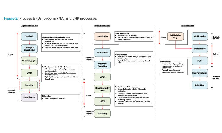
This section will focus on oligo, mRNA, and LNP manufacturing processes (see Figure 3 for a block flow diagram [BFD] representation of each of these processes) and segregation requirements associated with the different manufacturing operations.
The mRNA manufacturing process will require a DNA template for the IVT reaction, which can be purchased or manufactured in-house through an E. coli fermentation process. Purchasing the DNA template material will remove a distinct manufacturing process from the in-house requirements but can add cost and business continuity risks, as market supply chains for this ingredient are currently very stretched.
Oligonucleotide synthesis process
The oligonucleotide synthesis process involves the building of the oligo molecule chains on a solid matrix, which is packed into a column similar to that of a chromatography column. Each molecule chain is built up through a series of coupling reactions. In these, each of the amidites (the building blocks used in chemical synthesis of oligos), solvents, and reagents are transferred to the column and flushed through the static bed via the synthesizer skid. Once synthesis of the RNA molecule chain is complete, the cleavage and deprotection steps are carried out. The bed is immersed in an ammonia-based solution and heating is applied to remove the protecting groups and cleave the oligo molecule chains from the resin bed.
The product, now in solution, is collected in a pool tank and ready for purification. The synthesis manufacturing process needs to be carried out in a fully closed manner due to the hazardous nature of the solvents involved. There is also a negligible risk of contamination of the chemical-based process, so these operations are typically carried out in a controlled-non-classified (CNC) area.
The downstream process steps typically involve chromatography (ion exchange or reverse phase) and ultrafiltration/diafiltration (UF/DF) (the order of operation may change depending on the process). The chromatography step purifies the product, and the eluate is collected in fractions. The composition of each fraction is then tested, and the appropriate fractions pooled ready for transfer to the next process step.
The UF/DF step then concentrates the product to the appropriate drug substance (DS) concentration and the carrier solvent is removed and replaced with the formulation buffer solution. The purification process is typically carried out in a ballroom manufacturing suite, with all process steps being completed in a closed manner. Flammable solvents will potentially be required for the initial part of the purification process with the final formulation, following the UF/DF step typically being an aqueous solution. The purification suite is commonly a Grade D area.
mRNA manufacturing process
The mRNA manufacturing process would again be split into synthesis and purification stages but is a more aqueous-based process with some flammable solvent usage. If the DNA template for the mRNA synthesis is purchased, this will typically need to be linearized prior to the IVT process. The IVT process is typically carried out in a single-use mixer (SUM) or a single-use bioreactor (SUB). It is terminated through quenching and capping steps following transfer to a larger SUM downstream of the IVT reactor.
The crude mRNA product then undergoes a series of chromatography and UF/DF steps to remove impurities and produce the final DS formulation. There are a number of variations associated with the mRNA purification train, which include the use of flammable solvents for certain chromatography steps. Processes for mRNA purification may not involve flammable solvents, but certain chromatography steps may involve the use of concentrated ethyl alcohol (EtOH) or 70% acetonitrile (ACN). Single-use equipment is commonly used for the process steps associated with aqueous solutions.
Stainless steel (SS) equipment is required for any steps that use flammable solvents due to the electrically nonconductive nature of single-use plastics. The chromatography steps that involve the use of flammable solvents can potentially be installed in a defined hazardous area within a larger ballroom suite.
The synthesis and purification operations can either be carried out in separate manufacturing suites or a common ballroom suite based on closed-process operations. The linearization process prior to the IVT step should potentially be in a dedicated manufacturing suite for flexibility of operation. This should operate on a campaign basis and the linear templates should be frozen, staged, and ready for use.
LNP process
The oligo and mRNA components then need to be encapsulated in LNPs. The lipid solution is made up by adding the lipid components to a volume of concentrated EtOH and dissolving at a temperature of 30°C–40°C. The encapsulated product is then produced by feeding the lipid solution and the DS material in parallel feed streams into the encapsulation system (microfluidic platform8 or impingement jet mixer 9). The process outlet is then diluted with an aqueous buffer solution on exiting the encapsulation system and fed directly to a UF/DF system for removal of the EtOH .
This operation is time sensitive due to product stability considerations. Any final formulation adjustments will then be made, and the product will be filtered into bags and frozen ready for transfer to the fill/finish area or facility. The lipid solution prep would typically be carried out in a dedicated area adjacent to the main process suite.
The main process suite should then be a ballroom with the encapsulation system (and potentially the downstream UF/DF system) being installed in a defined hazardous area within the larger ballroom suite.
The non-viral synthetic approach would require three defined manufacturing areas for flexibility of operation. A dedicated oligo manufacturing area, mRNA manufacturing area, and LNP processing area will allow parallel manufacturing of each of these processes. The main support functions associated with these operations (solvent storage and distribution, buffer prep, and process utilities), can potentially be shared, as long as risk mitigation against cross contamination is ensured through the design. The appropriate risk mitigation and quality risk management (QRM) strategies should be assessed through facilitated risk assessments.
Viral Delivery
Viral delivery may be done through a viral vector (VV), such as AAV or lentivirus (LV). VVs are commonly used in gene therapy or cell therapy applications and have applications for both in vivo and ex vivo gene editing. Similar to gene therapy, a VV is manufactured to code for a gene of interest. In this case, the gene of interest delivers the instructions to the patient to manufacture both the gRNA and the endonuclease protein. Although the use of VVs has had success in commercial cell and gene therapies (C>s), cost, safety, manufacturing scalability, and the ability to redose patients are valid concerns.
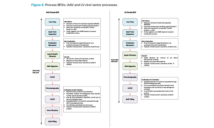
This section will focus on VV manufacturing processes. With respect to gene editing, AAV is typically associated with in vivo processes, and LV is mainly associated with ex vivo processes, with some in vivo candidates in development. Figure 4 shows a BFD representation of these types of processes. Different types of VV processes have different typical capacities and variances in the specific process trains, but the core process stages are similar.
The process starts with inoculum prep activities, which encompass a number of cell expansion steps carried out in flasks installed in a shaker incubator. Preparation of meach flask involves open operations that are carried out in a Type 2 biosafety cabinet (BSC), typically installed in a Grade C environment. This is followed by the seed train operations, which are carried out in a combination of wave bioreactors and stirred tank (STR) bioreactors. Single-use technology (SUT) is typically utilized for these steps in VV processes because SUT is flexible and is a risk mitigation measure against cross contamination.
The upstream process (USP) then culminates with the production bioreactor step when the transfection process is carried out a nd the viral particles are produced. SUT facilitates fully closed operation and allows the manufacturing area to be Grade D or potentially CNC. The tran sfection solution preparation needs to be carried out near the SUB and will potentially involve an element of open processing. If this operation is carried out in a Type 2 BSC, then this would drive a Grade D environment as opposed to CNC.
The specific clarification steps vary between AAV and LV. AAV is typically an intracellular process, requiring a cell lysis step, whereas LV is typically an extracellular process. The process steps for these two types of processes are carried out in similar equipment. The downstream processing (DSP) steps then encompass a series of chromatography, filtration, and UF/DF steps prior to filling the bulk DS into bags.
Another potential difference between the AAV and LV processes is that an AAV process may include a virus filtration step for mitigation against adventitious agent contamination. This step is not possible for an LV process due to the diameter of the viral particle compared to the nominal pore size of a virus filter. The clarification and DSP operations typically utilize SUT. Therefore, physical segregation between the pre- and post-viral areas for an AAV process is not specifically required based on closed processing. If the facility is designed for flexible and multi-modal operation, having the full DSP operations in a single ballroom suite is a reasonable approach for consistency between the manufacturing processes.
If the therapy is an in vivo process, then the bulk DS is frozen and staged ready for transfer to the fill/ finish area or facility. VV processes involve small-scale, single isolator filling operations, which are commonly carried out in a separate area of the same facility as the DS manufacturing operations. If the therapy is associated with an ex vivo process, then the drug product (DP) is produced through a small-scale cell therapy manufacturing process prior to a manual or semi-automated filling process. The cell therapy process may be carried out in a separate area of the same site as the DS manufacturing operations, or the frozen DS may be shipped to a different site.
GENE EDITING RETROFITS: FROM MAB TO CRISPR
As discussed in the prior section, facilities for the manufacture of gene editing therapeutics can take on many formats and modalities depending on the technology used. This section will compare the manufacturing processes associated with the non-viral and viral gene editing delivery mechanisms, with that of a typical mAb manufacturing process. This will help determine which of these approaches would be most suitable for retrofitting a facility previously utilized for manufacturing of mAb products.
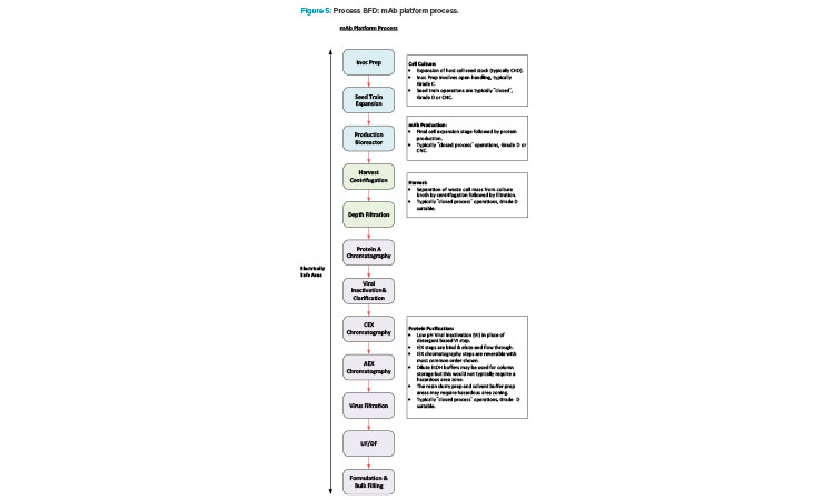
Manufacturing of mAb products is now quite a mature industry sector and a platform manufacturing approach is very common across the industry. Figure 5 shows a BFD representation of a typical platform approach.
Manufacturing VV products has a high level of synergy with the mAb manufacturing process. Additionally, there is commonality in the support functions between these modalities with both requiring media for USP operations, buffer for DSP operations, and similar process utilities. Manufacturing a gene editing therapy that uses an in vivo delivery platform would therefore be a good fit for a facility conversion. Ex vivo administration of gene editing therapeutics requires a cell therapy manufacturing component. This involves an additional distinct manufacturing process that is significantly different to a mAb process.
The non-viral synthetic approach discussed in the previous section would be more challenging to retrofit due to the differences in design requirements for the manufacturing areas. The manufacture of oligos potentially requires extended ceiling areas to facilitate installation of head tanks and uses large volumes of flammable solvents. Buildings associated with the storage and use of flammable solvents need to align with the requirements of the International Building Code Group H buildings.
This is not necessarily required for a mAb manufacturing facility, so conversion to this type of facility may have implications for the general building design that could be very costly.
The manufacturing suites are also electrically classified with all fixtures and fittings within the suite required to be spark-proof and intrinsically safe for operation around flammables. In the US, the National Fire Protection Association 70 10 or the National Electrical Code define these requirements, whereas in the EU, ATEX directives 11 and the International Electrotechnical Commission standards 12 must be followed.
Although many formats could be accommodated given sufficient time and funding, the modality that can most readily be retrofitted into a mAb facility, for moderate capital and time investment, is VV manufacturing. The facility could then be used to produce gene editing therapies for an in vivo viral delivery platform and support ex vivo cell therapies produced elsewhere.
VV AND MAB SYNERGIES AND DIFFERENCES
Having identified the viral delivery approach as the most suitable when looking at the conversion of a mAb facility, this section will now investigate the commonalities and key differences between mAb and VV manufacturing operations. Every facility has its own nuances and therefore every facility conversion will be different; this section will focus on the main considerations when comparing the different operations.
Equipment and Scale
Often, mAb and VV facilities have many similarities in terms of equipment, facility design, and approach. Converting from one process to the other is feasible with a few considerations in mind. Both are divided into USP, harvest, and DSP operations. Facility size and capacity can vary greatly, with the throughput determined by the quantity and size of production bioreactors. For mAb, this can range from 2,000-liters (L) SUBs to multiple 20,000-L stainless steel bioreactors. The production SUBs associated with VV facilities typically range from 200 L to 500 L, with the largest currently in operation being 2,000 L. VV facilities heavily favor single-use equipment for flexibility to accommodate shifting throughput targets and risk mitigation against cross contamination, which is paramount when working with vectors. Converting an existing asset will potentially involve an older facility, which may comprise more SS equipment with some degree of a hybrid approach for certain operations.
The process support and process utility systems associated with the original asset will be similar to those required for the new manufacturing operations and therefore may be able to serve the new facility with some modification.
Facility Design
With mAb facilities, the industry has both facilities with distinct USP and DSP suites, as well as a more progressive ballroom approach, where all unit operations occur within the same room. Manufacturing of different products in parallel in the same area is permitted for mAbs from a regulatory standpoint, provided a suitable QRM strategy is in place. For conversion of older assets, the facility design will potentially have a more conservative approach with a greater degree of physical segregation. For example, the DSP train may be split into three separate suites: viral inactivation, pre-virus filtration, and post-virus filtration.
Segregation points in the older asset could be beneficial for multi-product manufacturing of VV products. The difference in scale between the mAb and VV DSP operations could potentially allow these suites to be used for separate DSP trains which would facilitate parallel manufacturing of different advanced therapy medicinal products (ATMPs). VV facilities tend to have segregation of the USP and DSP operations or segregation at the V- / V+ boundary (between the N-1 and N stage SUBs). Segregation at the V- / V+ boundary provides flexibility of operation because this is the point where the product is considered an ATMP (based on a transient transfection approach)—and the point where parallel manufacturing of different products in the same area, without adequate containment measures, is not permitted 13. Additionally, VV facilities often incorporate the DP manufacturing in the same facility as the DS manufacturing. In contrast, the DS and DP operations associated with a mAb process are commonly carried out at different sites .
Biosafety Level
Most mAb facilities are either good large-scale practice or biosafety level 1 (BSL-1), whereas most facilities for VV manufacturing are either biosafety level 2 (BSL-2) or biosafety level 2 enhanced (BSL-2+). The manufacture of BSL-2 therapeutics has specific requirements for the handling of both product and waste materials to ensure safety of personnel and environment. Retrofits that may be required include the addition of the following:
- A liquid biowaste inactivation skid to serve all DSP operations
- A deactivation autoclave for solid waste (mainly single-use consumables)
- Airlocks with appropriate pressurization schemes for containment of any aerosolized VV particulates
- Handwashing sinks
- Room sterilization using vaporized hydrogen peroxide (VHP), depending on the production requirements and risk tolerance between campaign changeovers
cGMP Flows
The movement of personnel, materials, and waste through a facility is one of the key attributes that is difficult to retrofit later. Most mAb facilities employ a bidirectional approach to movement of personnel and materials, as the products and processes have low biosafety consequences. Most processes are functionally closed, which reduces the risk of contamination.
In contrast, the V+ areas of VV facilities tend to employ unidirectional flows of personnel and materials. This approach facilitates isolation of each applicable manufacturing suite from the surrounding area by having a pressure regime where the entrance airlock is a pressure bubble and the exit airlock is a pressure sink. This is especially critical for multi-product VV facilities because cross contamination between products is a key concern.
This is the typical approach, but not a stipulated regulatory requirement. The EU regulatory guidance that relates to manufacture of mAb products is the EudraLex, Volume 4, Annex 2 14. This indicates that the layout of the different manufacturing areas needs to appropriately mitigate against the risk of cross contamination between process stages or products using QRM principles 14. The EU regulatory guidance that relates to manufacture of VV products is the EudraLex, Volume 4, Part IV. This indicates that the manufacturer should take a risk-based approach to ensure the quality of the ATMP products that they produce 13.
Manufacture of mAb products is a mature industry with established QRM principles. The industry has evolved over time, enabling more robust knowledge-based outcomes to risk management. VV manufacturing is still a relatively new commercial landscape, with knowledge and processes rapidly evolving. Consequently, this is reflected in the implementation of QRM processes and the acknowledgement by regulatory authorities that “a certain level of flexibility” 13 is appropriate based on the outcome of the QRM process.
CONCLUSION
With the approval of the first gene edited therapeutic in 2023, the field of gene editing shows promise. Additional commercially approved products are likely in the future. Gene editing therapies have the potential to provide long lasting, if not permanent, cures for several devastating genetic diseases and applications in oncolytic therapies. With a greater focus now being placed on sustainability when it comes to development of new facilities, there is likely to be a greater emphasis on repurposing of redundant or low-occupancy assets instead of building new facilities. The most applicable approach for conversion of a mAb facility into a gene editing manufacturing facility is the viral delivery mechanism for an in vivo therapy (or VV component of an ex vivo therapy) . Conversion of an existing asset also has the potential to increase speed to market compared to building a new facility, provided that the modifications are not too extensive.15
